Test circuit and code for a Hewlett Packard HDSP-2490 display
One of the component cabinets I bought for the MakerSpace at the Dunstable Downs Radio Club rally in May turned out to contain a large number of 1970s-vintage Hewlett Packard HDSP-2490 LED displays. These are 4-digit dot matrix displays; each digit is around 8mm high:
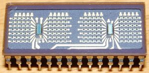
They could be termed ‘semi-smart’ displays – the two small chips visible in the photo are shift registers which hold the row data for each display. Data can be clocked into these registers. External multiplexing is then required for each column.
They seem to be sought-after on eBay, so we needed a way to test them.
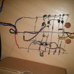
This display is a little tricky to drive, since each column has 28 LEDs and can potentially draw over 400mA with all segments lit, as I found out during initial tests. When driven by a microcontroller the average current is much less since they are multiplexed. However, the column driver circuits need to be able to source substantial currents. This is a picture of a test circuit I came up with, using an Arduino nano clone as the controller:
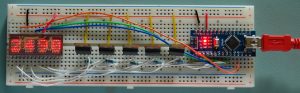
Unfortunately you can’t use a driver IC such as the ULN2803A, since they can only sink current and not source it. I have used TIP122 Darlington pairs in an emitter follower configuration. This drops about 1.2V, but the chip has constant-current drivers which only require 2.4V for full brightness.
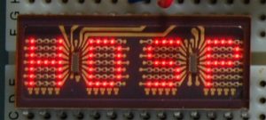
A close-up of the display:
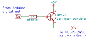
Here is the circuit diagram for one of the five column drivers:
I have made the driver code available on GitHub.
The datasheet for the display: HDSP-2490.
 Previous Post